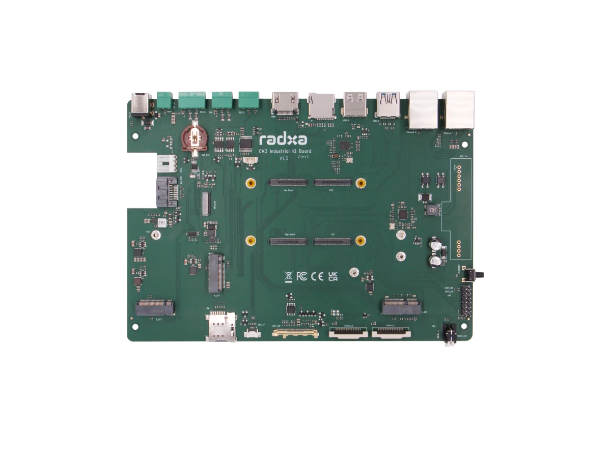
Radxa CM3I IO Board
Radxa CM3I with Radxa CM3I IO Board
Quick Functional Verification of 4x 100 Pin

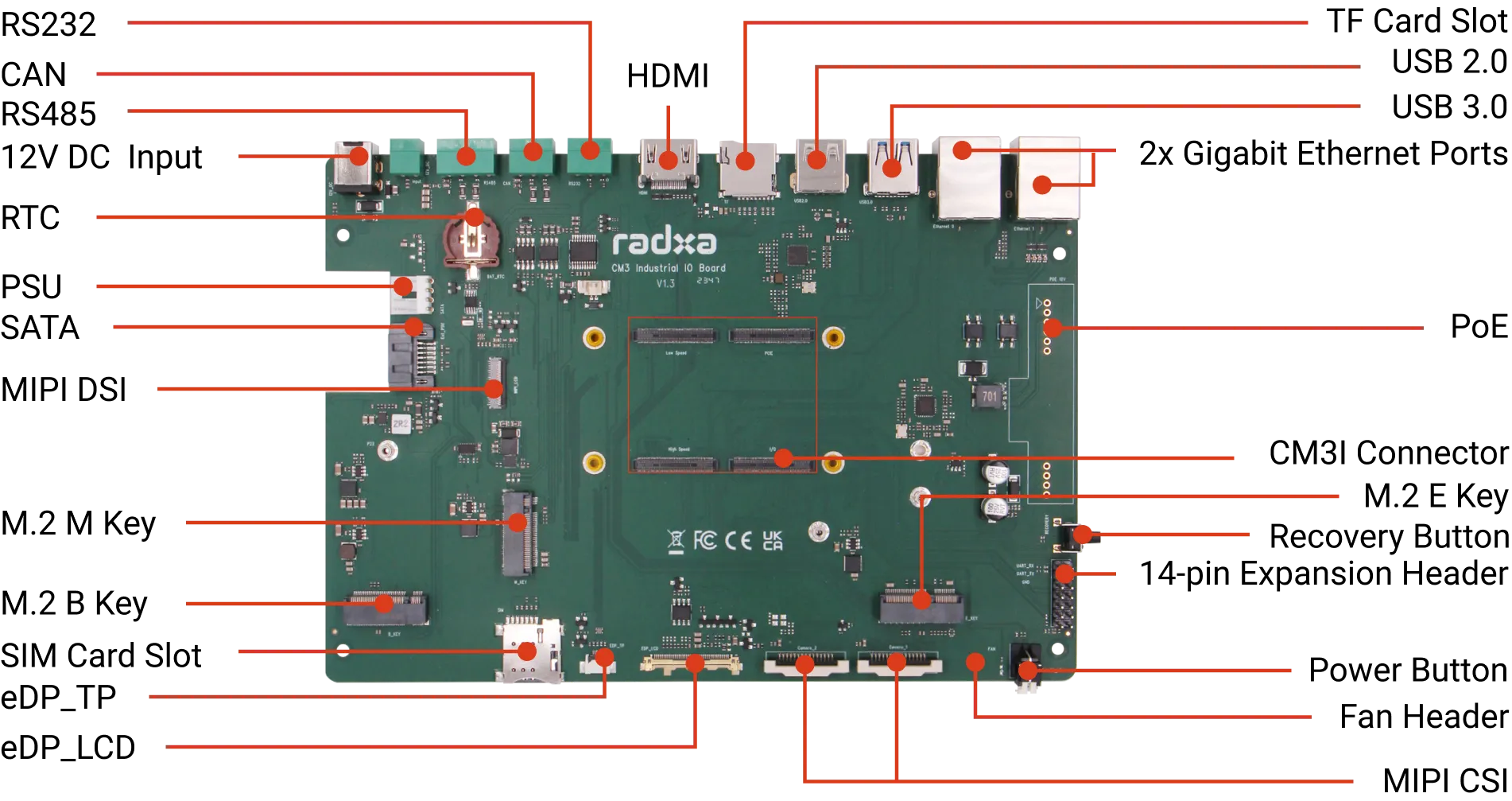
Interface Details
Serial Port
1x RS232
1x RS485
1x CAN
Video
1x HDMI
1x eDP with Touch Panel
1x MIPI DSI
Camera
2x MIPI CSI
Storage
1x Micro SD Card
SATA
1x SATA 3.0 with PSU
USB
1x USB 2.0 HOST Port
1x USB 3.0 HOST Port
Ethernet
2x Gigabit Ethernet, one of which supports PoE
M.2 M Key Connector
1x M.2 M Key Connector for 2280 NVMe SSD
M.2 E Key Connector
1x M.2 E Key Connector for Wi-Fi / BT
M.2 B Key Connector
1x M.2 B Key Connector with SIM Card for 4G Mobile Network
SIM Card Slot
1x SIM Card Slot for 4G Mobile Network
Button
1x Recovery Button
1x Power Button
Fan Header
1x 4-Pin Fan Header
RTC
1x RTC Battery Seat
The terms HDMI, HDMI High-Definition Multimedia Interface, HDMI Trade dress and the HDMI Logos are trademarks or registered trademarks of HDMI Licensing Administrator, Inc.
CM3I IO Board Works with
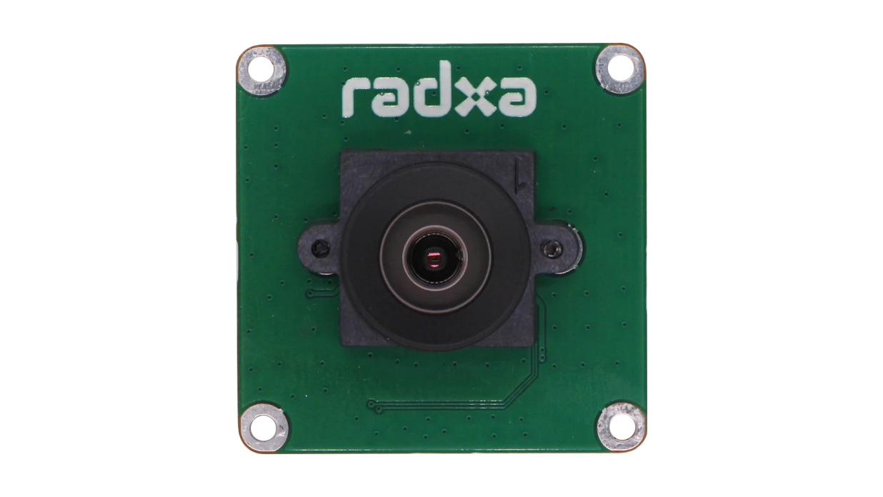 Radxa Camera 8M 219
IMX 219
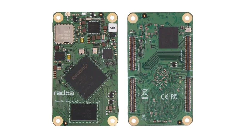 Radxa CM3I
A Feature Rich Industrial Embedded SoM
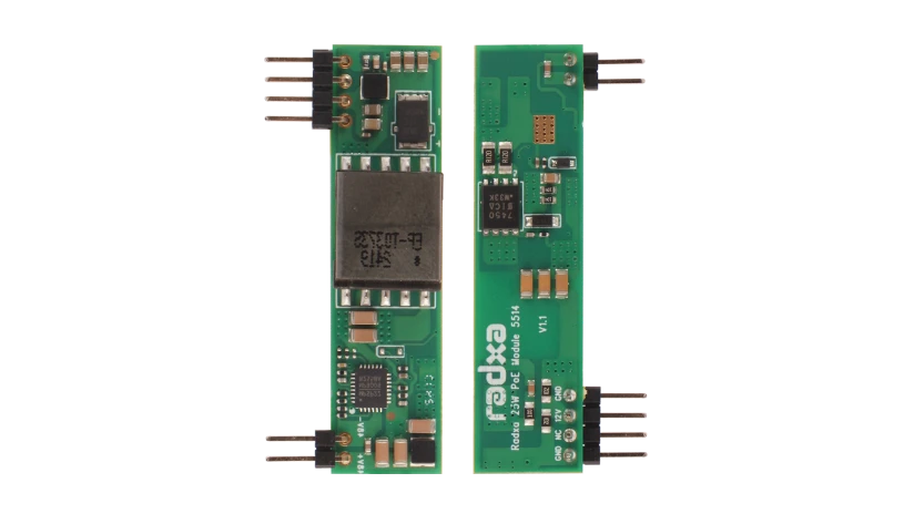 Radxa 25W PoE+ Module 5514
Compact PoE Module
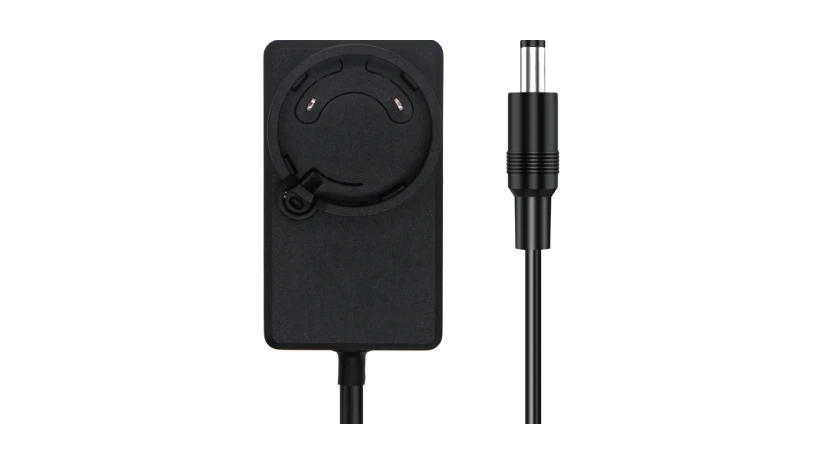 Radxa Power DC12 36W
Specialized for Radxa SBCs
 Radxa Display 8 HD
An All-in-One Touchscreen Module
 Radxa Display 10 FHD
10-inch FHD Touchscreen Module
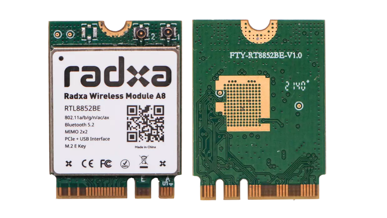 Radxa Wireless Module A8
WiFi 6 + BT 5.2 Dual Mode
